
Coil Winding
| This is my home made monotube coil winder. It has been used to wind pancake coils (as it is doing here) and helical coils and frusto-conical coils and the kind of wide spaced helical coils that are used for Ofeldt boilers. Here it is shown winding half inch schedule 40 black iron with welded seam. This is good enough as it has an 8,000 psi burst strength. We have wound everything from ¼” to ½” 316 Stainless to 1” schedule 80 black iron. | 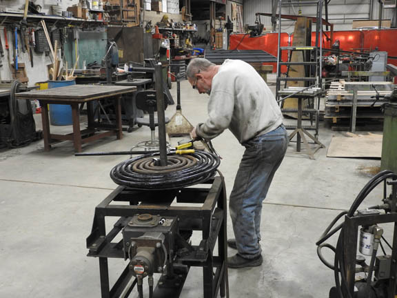 |
|
(Note: Click on a picture to see a larger view and then use your browser to enlarge it further.) |
||
 |
Usually we take a standard 21’ length of black iron pipe and make it into an 18” diameter pancake coil. Today we are taking three lengths of standard 21’ black iron, butt-welding them end to end and winding a double pancake coil 22” in diameter. The beauty of this system is that one does not need to do a weld in the center. That is very difficult to do and involves a lot of heating with a torch and beating around and trimming with a cutoff saw. It is not easy to work in the center small space and do a good weld. When winding a coil it always takes one or two tries to get things sorted out as we forget some of the details over the intervening years. Here we are fighting with the bottom coil as the windings are trying to climb over each other. We have solved this technical problem later on. | |
|
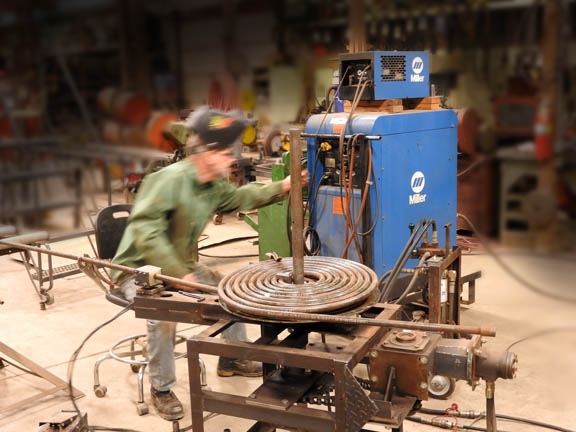
| We have a hydraulic power pak (not shown) that powers a small hydraulic motor that is bolted to a large worm drive gear box with the final drive being a very heavy chain and about a 3-1 further gear-down ratio. We want to turn the table slow enough so that we can see what is going on and stop it before we get in too much trouble. We are doing somewhere in the one to two rpm. That gives us plenty of time to get our fingers out of the way. | 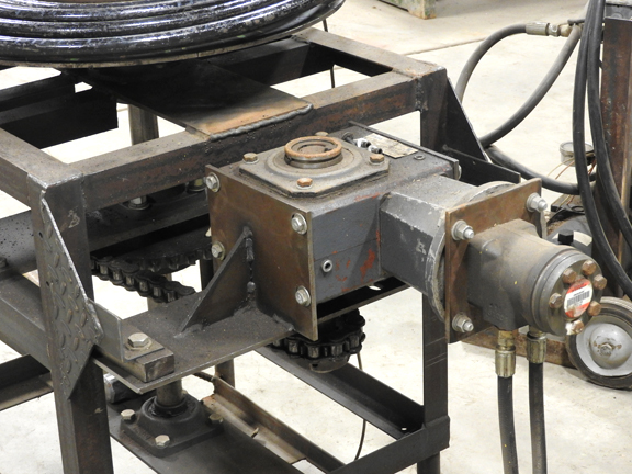 |
|
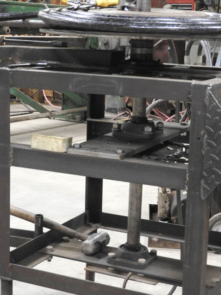 |
We start with a heavy angle iron welded table. We need a 4’ long vertical shaft 1 ½” diameter that is held in place by three heavy duty pillow blocks. Two pillow blocks will not work as there will be bowing from all of the side-loading. | |
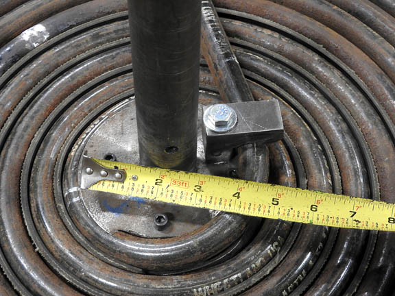
| The rotating table is, fortuitously, 22” in diameter and we are making 22” coils today. We start with a center mandrel that we machine for the diameter of the pipe or tubing and we are going with a 4” diameter center opening as little is gained by making that initial bend any tighter. We are not getting any flattening or distortion with this diameter and this system. To make the initial “U” bend we clamp the pipe tightly to the outer rim of the table and then pull the free end of the pipe through a nylon split block that is adjusted here with 5 bolts. It is important to put a lot of pull on the pipe. That helps hold the curve so that it does not spring out much. That also | 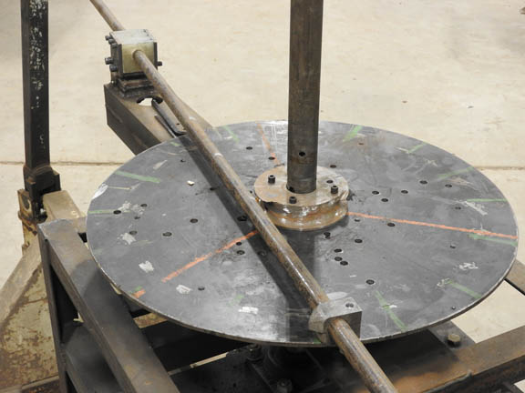 |
|
| keeps the pipe from flattening and the reason is that we are trying to come close to or exceed the modulus of elasticity of the pipe on the outside of the bend. We have gotten a feel for how much to tighten the nylon blocks by how much the machine grunts and chatters. As the coil diameter increases the forces, likewise, increase and thus the bolts are continuously loosened a little. When using welded pipe instead of drawn-over-mandrel (DOM) pipe it is important to orient the seam to the inside of the coil. When butt welding two pieces together the weld needs to be chalk marked do insure lining things up. With this making of a double coil we end up with one of the coils having the seam on the inside and one section with the seam on the outside. The main importance is to not have the seam up or down where the fire will hit it. | ||
 |
So then we make the initial 180 degree wind. We have to go a little ways past to compensate for the natural spring-back. The power pack is equipped with a control valve that changes the direction of flow of the hydraulic fluid. It is always important to reverse the rotation and back off on the winding before loosening or taking apart the nylon blocks. If the end of the coil comes loose before it is unwound, it will uncoil about one complete turn and the pigtail end of pipe will come around really fast and if anyone is close their entire insides will be rearranged. | |
| A person should stop and think and meditate and then cogitate some more before unbolting anything. Or maybe a safety chunk of iron could be welded to prevent such an accident from happening. | ||
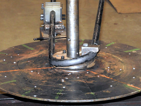
| In order to wind two pancakes at a time, the hair pin bend is kicked up about 1 ¼”. You will see the jig in place (it will be explained later on) that acts as a wedge so that during the first turn the pipe as a smooth transition to go on the outside of the first inner coil. | 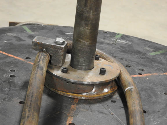 |
|
 |
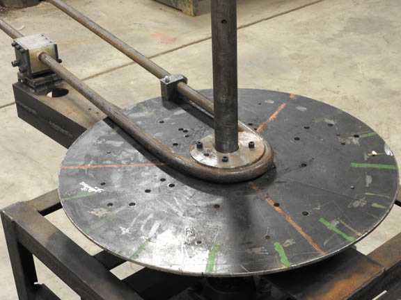
Here is the view from the other end of things showing the pipe ready to draw through the nylon blocks. This is the trick to making two pancake coils without doing any center welding. The initial “U” bend is kicked up so that there will be about a quarter of an inch clearance between the two pancakes. This can be easily set for whatever distance one wants. It also shows the ramp part of the jig that gives a smooth inner surface to the first turn on the second coil. | |
| This is a very important and clever part of the jig and it is difficult to fabricate. As you can see we are trying to do two things here with the initial full turn. We need to ramp the first full turn out for the pipe diameter plus ¼” so there is a smooth transition (the right side of this jig) all the while holding the pipe out (the left side of this jig) so that it does not get wedged under the initial hairpin curve or climb on top of it. The ramp up is shown in photo 8. | 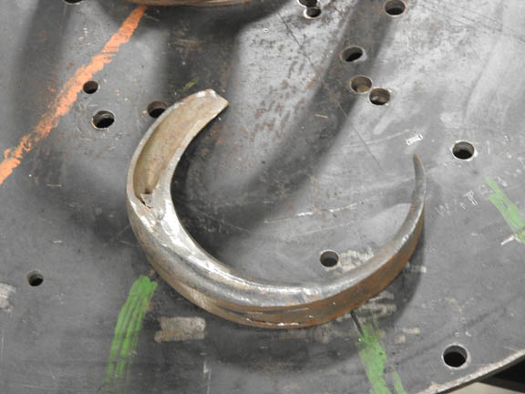 |
|
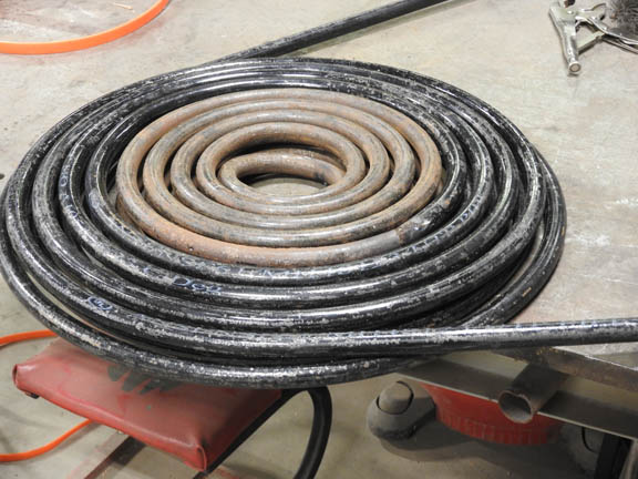
| We did not make this clamp strong enough to keep the pipe from pulling through and so there is a little spot weld needed which can be cut off and ground down afterwards. You can just see this weld if you know where to look. Also note that we are done welding the first coil. It has been reversed and relaxed to it has sprung out for spacing. You can see butt weld about 4 coils in, also the change in color as we used black pipe at first and then rusty pipe | 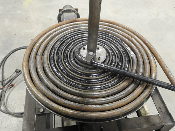 |
|
 |
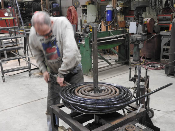
This shows the first coil done with the conveyor belting spacing in place and all pulled tight. This is before the table is backed off so the pipe can spring apart. | |
| Here it is relaxed. You will note that the conveyor belting spacing is only used for the first 4 or 5 coils. The outer coils are wound tight against each other and they naturally spring apart. Surprisingly, the pipe winds tight against itself. | 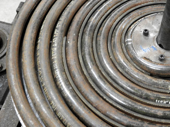 |
|
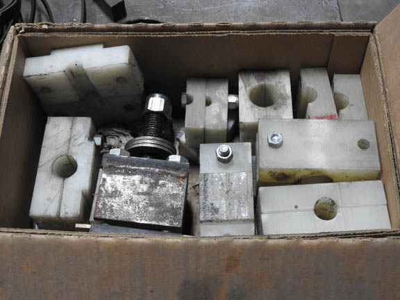 |
Here is a whole box of nylon split clamps made for every possible diameter of pipe or tubing. There may be a better way of doing it but this works just fine for us. We just hold things together with bolts and then hand adjust while winding. It takes less tension as the coil gets a larger diameter. The clamp is completely taken apart when taking the coil off the table. | |
| Here we have finished one 22” coil and flipped everything upside down to wind the second coil. The coils are always wound flat on the table. Even then it is a trick to keep them lined up precisely so that they do not climb over or under each other. There is a lot of stress and pull on the pipe so there is a lot of compressive force. The nylon block is being reassembled. You can see that the coils have sprung apart a little more than the planned for ¼” spacing. This indicates that the first coil is always the test coil. We get spacing between the coils with a long strip of conveyor belting about 7/8” wide that is ground at an angle at the end. | 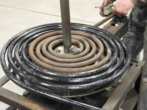 |
|
| This conveyor belt is fed in after the first full turn while the operator is careful to not run his or her fingers through the machine. Once it catches, then the hydraulic power pack operator (there are always two people needed to make these things) pulls the belting tight so that it winds properly. Usually belting is only needed for the inner half of the diameter. In this initial winding we left it in for the full diameter and, as you can see, the coil sprung too far apart. It works better to use a shorter length of belting and wind the outer half of the diameter iron to iron. Because of the distance between the nylon block and the outer diameter of the coil there is always about a 3’ pigtail. Always remember to back off about one full turn of the table before starting to loosen the nylon blocks. That pigtail can be pulled by hand around to tighten up the coil and then it can be wired to spacers or welded to something to force it into a tighter coil if you make an error such as this. | ||
 |
The final assembly of the coil stack is to cut off the pigtails so that the next double coil is all lined up and then butt welded together. Spacers, which are usually short lengths of ¼” rod, are wired between each of the coils to hold things apart. When the iron gets hot it tends to sag and droop and so it needs to be wired up a lot. We use stainless wire and one of those stainless wire winding tools you can buy from Aircraft Spruce. | |
 |
||
| A good welding job is essential. We do TIG welding. There are two important preparatory tasks. |
| First, the ends of the pipes are ground such that they are champhered. And then when butted together there is a Vee so that the welding material can get in there to hold the pipe ends together. This is easier than trying to get penetration all the way through the thickness of the pipe. Because the pipe is cut with a cutoff saw or a hacksaw, a die grinder is used to smooth off the resultant burr on the inside. | 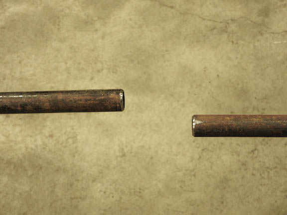 |
|
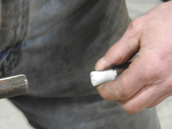 |
Next, is the most important part of welding. A small piece of ceramic felt, which is a type of high temperature insulation that one always has around for wrapping the fire box or the boiler casing, is cut and tightly wrapped and then inserted half into one of the pipes. The other pipe is carefully twisted over the part of the ceramic that is sticking out. This keeps any weld flashing or gobs of melted welding rod or anything from sticking into the center of the pipes. The ceramic material is easily blown out afterwards with compressed air. It is important to remember to remove it and to count the pieces or the boiler (steam generator) will not work and you will never figure out why not. | |
| Some people machine I little thin piece like a coupling that fits inside the pipes lining them up and keeping the gobs of slag from getting inside. This does some flow restriction, but it is not a big deal. | ||
| Here is a coil made for an Ofeldt style boiler. When making an Ofeldt keep in mind that half of the coils are right handed and half left handed. Even more important, space the coils apart about 1 ¼ times the outer diameter of the pipe. Because the coils have to mesh and they are slightly angled in relation to each other they need a little extra room. | 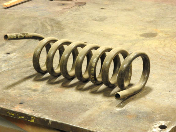 |
|
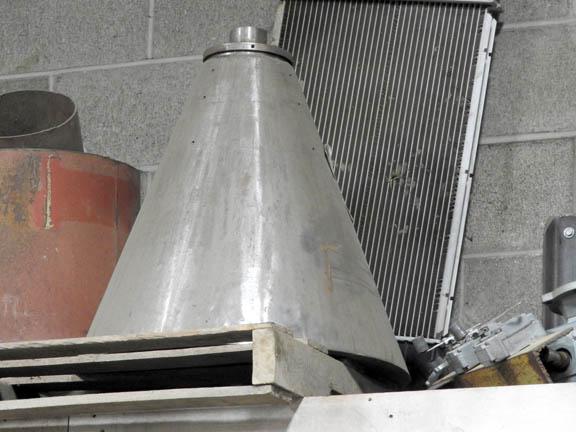 |
Here is our form for a frusto-conical coil. There is a trick to winding these things. It will become apparent that the coils, when wound tight, tend to go from the larger diameter part of the cone to the smaller part. Instead of fighting this all day long, just start at the small end. There are two ways to space the coils. One way is to chain one end to a tree and the other to a tractor and pull it apart after it is wound tight. The other way is to cut lots of little pieces of quarter or three-eighth inch flat stock and insert these every few inches while winding to space the pipe apart. After the first few unpleasant experiences you will learn to hold these spacer pieces with a pair of pliers instead of with your fingers. Most people learn fast about that trick. | |
We are not showing how to wind a helical coil water wall. First find a heavy piece of pipe the right diameter and bolt it to the rotating table. Then mount the nylon clamping piece on a sliding vertical heavy duty pipe. We often use a hand cranked acme thread rod to raise the pipe as it winds. This is also how we do the Ofeldt coils. Because the diameter of a water wall needs to be precise we keep tension on the coil when done winding and put in a lot of short welds to hold the whole water wall together. Then it does not spring back when the tension is released. The most difficult part of winding coils is making all of the clamps and jigs and mandrels for starting and figuring out how to use them. Winding coils is a daunting task until you have successfully done it once and then it is good fun, almost magic. Many people try to wind copper coils and they are always flattening and crimping and messing up. They can be filled with sand or shot or some kind of wax to keep them from doing this. I find it much better to never use copper. Copper will quickly over-heat and anneal when the water pump fails and so there is no reason to use it. We like ½” black iron because it is cheap and available. It is much less expensive than 3/8th” which is strange. I was asked once to wind a two-path coil with every other pipe in the pancake being in a different water pump circuit. It may be possible to do, but I would be an old person before getting it set up properly. When doing multi-path always have a separate water pump for each path. A simple “Y” is not going to cut it. Maybe a slowly rotating rotary valve will get the distributing done. These can have lots of tolerance because some leakage is alright. |
||