
Steam Sterilizer
| Boiler: | ||
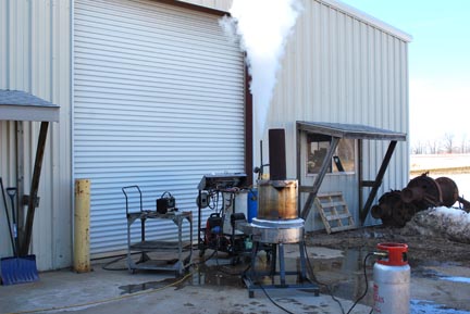
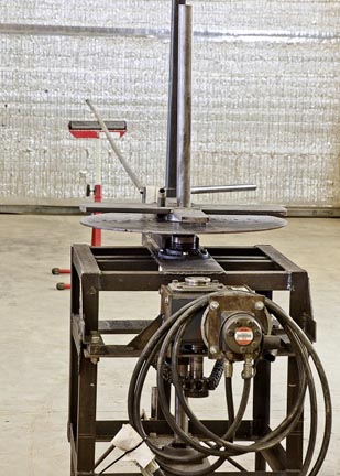
The purpose of this coil stack is to make steam to be injected as needed for heat sterilization. Therefore it exhausts at near atmospheric pressure. The test setup is with two propane weed burners at 400,000 btu’s each for a total of 800,000 btu’s. A variable speed dc powered squirrel cage fan supplies the air flow. It burns cleanly. Ultimately this coil stack will go on top of a pellet burner of one million btu’s and so both the shape and design were made to fit the existing pellet burner (supplied by a different company, and cleverly designed at that). It is all helical coils with the combustion gases being introduced at the bottom of the coil stack and routed to the 1 ½” annular passage around the outer circumference of the coils. There is a solid water wall on the very outside. The combustion gases then go toward the inside and exit through a 6” diameter stove pipe at the top. |
||
 |
||
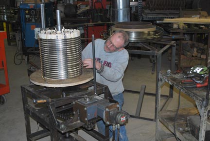
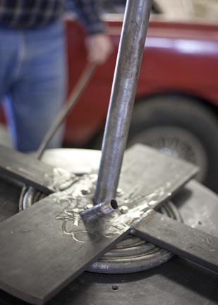
| Terry Stout securing the boiler tubing to the separators as it sets on the hydraulic coil winder. | ||
(Note: Click on a picture to see a larger view and then use your browser to enlarge it further.) |
||
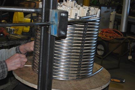
| This coil stack was made with 316 stainless with .035 wall thickness, with half being 3/8” od and half being ½” od. We wind from the inside out using thin strips of wood lathe for spacing between the helical coils and little thin stainless strips that we made ourselves punched into zig-zags for spacing between the tubes vertically. Things are tied together with stainless wire after each helical coil. The lathe is burned out after everything is finished. With this construction method we have complete control over the tube spacing in all three dimensions. Metal spacers are left in for spacing between the helical coils. | |||
 |
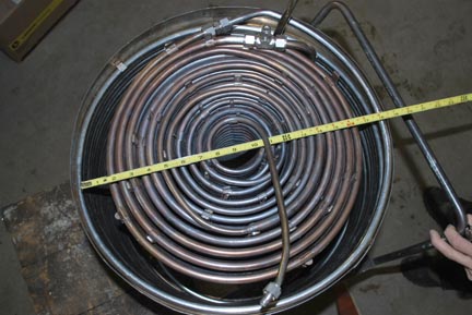
For the 3/8” tubing we have 6 helical coils from 3 1/8” diameter center line to 8 7/8” diameter center line with 24 turns in a coil for 230 lineal feet of tubing and 23 square feet of surface area. For ½” tubing we have 5 helical coils from 10” diameter center line to 15” diameter center line with 21 turns per coil and with a water wall 16” in diameter close touching for 32 turns. This gives a total of 477 lineal feet of tubing and 62 square feet. These ½” coils are spaced closer together than the smaller tubing because of the larger diameter of the helical coils and thus there is plenty of room for gas flow between the tubes. |
||
| The boiler on the hydraulic winder. | |||
|
|||
Total heat exchange surface is 85 square feet. These figures are for all sides of the water wall coil and so there will be effectively a little less square footage than that. When tested we were getting 300 degrees F stack temperature while getting combustion gas condensation on the inner coils. We were boiling a little over 1 ½ gallons per minute of cold water with an exhaust steam temperature fluctuating from 300 to 500 degrees F depending on the adjustment of water flow from our variable speed water pump. There was an 800 psi water pressure going into the coil stack when it was making maximum steam. We tested water flow without any heat and the back pressure was just under 100 psi, which would be the skin friction of water flow. Therefore steam flow was creating a lot of skin friction. At one million btu we expect to boil 2 gallons a minute. |
|||
We purchased the stainless tubing in 600 foot rolls so the only welding was at the junction of the 3/8” and ½” tubing. As we all know tubing is measured from the outside diameter and one has to subtract the .035 or whatever it is wall thickness twice to get the inside diameter. The superheater was buried one layer in from the combustion gas annular passage. |
 |
|
Our next prototype will be constructed from ½” schedule 40 welded black iron and for two reasons. The main one will be because city water with chlorine cannot be used anywhere around stainless or there will be pinhole corrosion holes in the tubing. For convenience we will go to black iron. The other reason will be larger size pipe for better steam flow and cheaper price. The assumption is that we will end up with enough square feet of heat exchange surface to continue having a low stack temperature. Also the layout of the next one will have the combustion gases going up the middle through a larger opening than we have here and passing through the helical coils to exit via a less than 1” annular passage at the outside. The reasons are two-fold. This will eliminate the need for much insulation at the outside of the coil stack and it will allow for the installation of a steam/water separator drum in the very middle. |
||
|
|||
 |
We plan on welding a lot of fins to this center separator drum, which will be in the 3” diameter range, to give a nice swirl to the gases assisting in the even distribution of the gases to the inside of the helical coils. The fins will be vertical at the bottom—the end where the fire is coming from—and each of the fin stacks as we go up will be slightly angled to that at the top they are completely horizontal. The fins will secondarily transfer a great deal of heat to this central water/steam separator drum which will be used as a water level controller for the boiler, thus boiling out the water as fast as possible. |
||
| We want a water level controller and one that does not become water-logged for ease of control if we want to use this as a steam source for a steam engine. When using a separator drum to control water flow into a monotube boiler it is very important that water be continuously boiled out of the drum. Otherwise it will become water logged and thus give a false reading of water level, stopping water pumping and burning out the coils. At another time I will explain why I am such an authority on how this phenomena works. The saturated steam will be pulled from the top of this central column to be run through a buried superheater. The system will give us a superheater of fixed length making it much easier to control than a conventional monotube steam generator which has, by definition and depending on the load, a superheater of highly variable length as the transition zone floats up and down in the monotube coil stack. Our hydraulic motor powered winder makes helical coils, pancake coils, spaced helical coils for Ofeldt boilers, and frusto-conical coils. |
|||
|
|||
 |
 |
|
| Coil Winder | Pancake coil being wound. |
Memo on the one million btu steam generator for sterilization work. Tubing: 316 stainless steel |
|||
Helical coils, measured to the center line for diameter 3/8” diameter tubing 1 3 1/8” 24 turns |
½” diameter tubing 7 10” 21 turns Water wall ½” tubing 12 16” 32 turns |
||
|
|||
| May 11, 2014 | |||
This is a steam generator that we made in the shop this winter, the cold one of 2014. It was designed to fit into a cylindrical volume that someone else had designed and made already that was located on top of a pellet burner of nominal one million btu’s. For many reasons it would have been better, maybe only slightly better, if the combustion gases entered the coil stack from an 8” tube in the center and flowed out radially. The combustion gases entry openings from the combustion chamber were already cast in ceramic and so we designed around that prototype. Not too much difference was made, except that much more insulation is needed because this thing is hot on the outside. Here we made the steam generator out of helical coils. The first reason is because we had the room to bring a plenum up around the outside of the coil stack, albeit with a water wall on the outside to cool things down a bit, and to have gas flow from the outside in. The second reason is because we had purchased stainless steel tubing in one thousand foot rolls and our coil winding technique meant that we did not have to do any welding between coils. We just went up and back down and up again making only one weld where we went from 3/8 to ½” tubing. |
|||
|
|||