
Williams Bus Engine and Boiler
Engine |
||
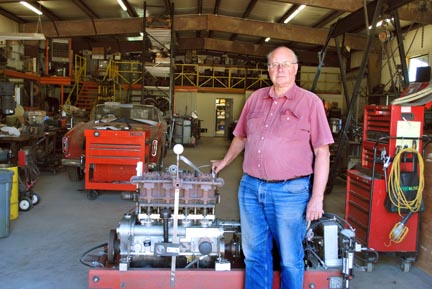
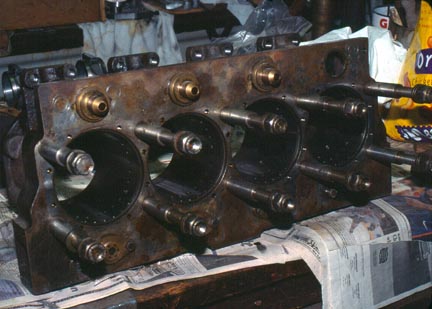
Tom with the Williams 265 c.i.d. bus engine, four cylinder, cross-head, single acting, uniflow, poppet valve with sliding camshaft, auxiliary poppet exhaust valves for use at long cutoff. |
 |
|
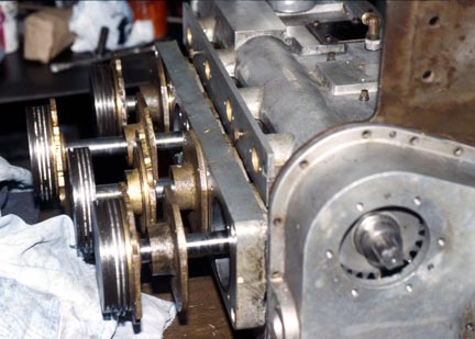
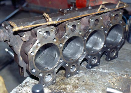
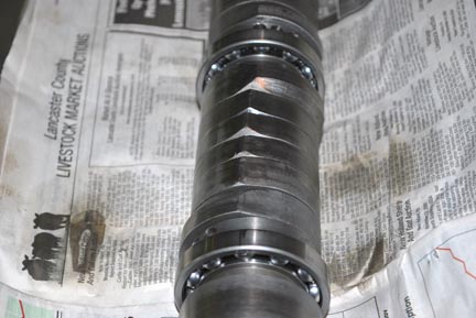
Williams 265 c.i.d. bus engine taken apart for CADing. This is the standard and final Williams design, single acting cross head, sliding camshaft, poppet valved, uniflow with a pressure relief valve in the head, in-line 4 cylinder. There is significant and measurable thermal expansion at the head end of the cylinder
There appear to be a couple of potential problems with this engine. The crankshaft does not have counter-balances with balancing being done with a weight at the end of the crankshaft. That is not pictured. Secondly the cam and cam followers are under high loads. The camshaft is assembled with a long key way machined into the relatively small diameter camshaft. A long |
||
 |
 |
|
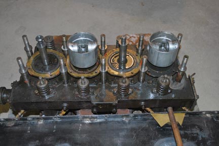
| Manzel oiler for the engine. Oil is injected into the side of the cylinder to oil the rings near bottom dead center. | Williams 265 c.i.d. bus engine showing the crossheads for the single acting pistons and the valve train. The sliding cams are down in the block. | |
 |
 |
|
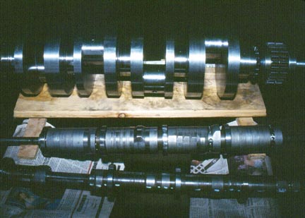
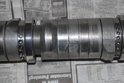
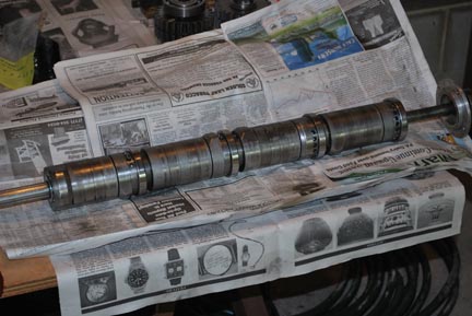
Photos of the intake valve camshaft and cam grinds for the bus engine. At each end are very long cutoff cams for starting out forwards and reverse. The cam grinds in between appear to me to be far too short to be practical. It seems that the Williams brothers were trying for the ultimate in efficiency, with little practical success. The other problem with this camshaft design is that the shaft itself is too small. There is a keyway cut the length of it with a long key that keeps the cam lobes lined up. When this wears a little the cams will shift during the rotation due to the strong valve spring pressure. This very slight shifting effectively shortens the cutoff even more. |
||
 |
 |
|
 |
 |
|
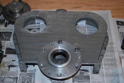
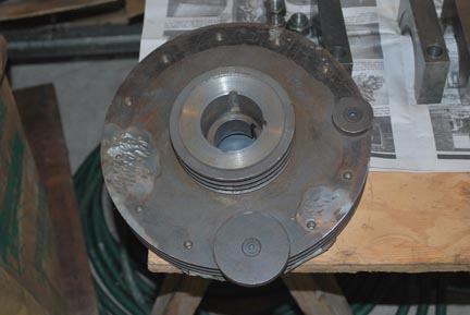
Heart shaped casting for the end of the block with openings for the two sliding camshafts. |
Flywheel showing balancing weights. The crankshaft appears to be machined from a billet and there are no counter-weights. | |
 |
|||
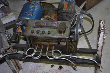
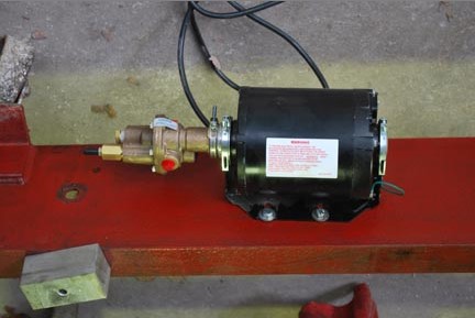
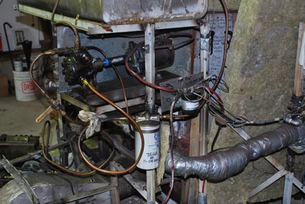
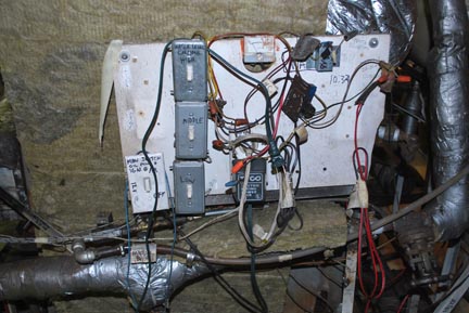
| A.C. powered oil pump. After scoring the crankshaft and two connecting rod big ends this oil pressure pump was added. It was turned on before the engine was turned over thus providing 100 p.s.i. oil pressure to the crankshaft bearings. | |||
Boiler Photos: |
||
(Click on a picture for a larger view, then enlarge it further with your browser.) |
||
|
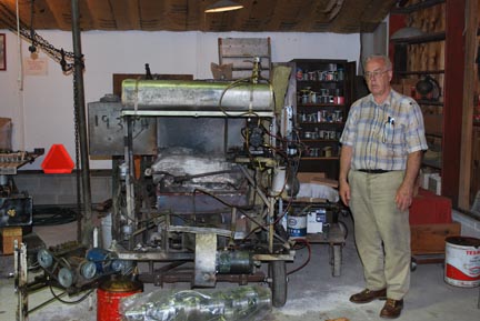
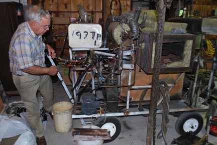
Peter Nuskey and the Green Monster boiler showing the end with the blower fan. This is a Babcock & Wilcox type of a boiler made by the famous Harry Peterson for Howard Landon’s Green Monster car, the one with a Doble “F” engine in it. It is being used as a shop boiler here to run dyno tests on the Williams bus engine. |
|
 |
 |
|
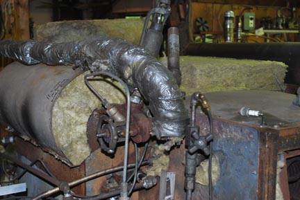
| Water pump for the boiler | Peter Nuskey and the smoke stack end of the boiler with two helical coils for economizers. | |
 |
 |
|
Top water/steam separator drum for the B & W boiler with insulated line taking steam over and down to the superheater. |
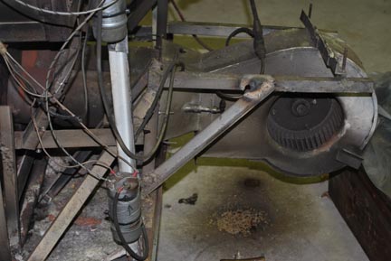
D.C. powered squirrel cage blower for the Green Monster boiler, 20 g.p.h. fuel oil burner. |
 |
 |
||
| Fuel pump end of the Green Monster boiler. | Water level control end of boiler. | ||
 |
 |
||
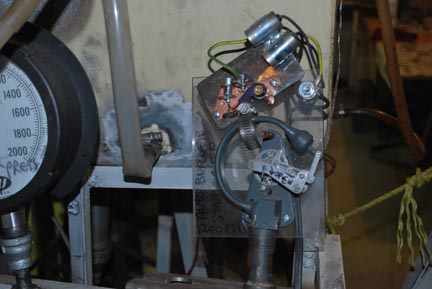
| The Green Monster Car | Bourdon tube pressure control switch for the boiler | ||
|