
Williams Victress Boiler and Engine
Boiler |
||
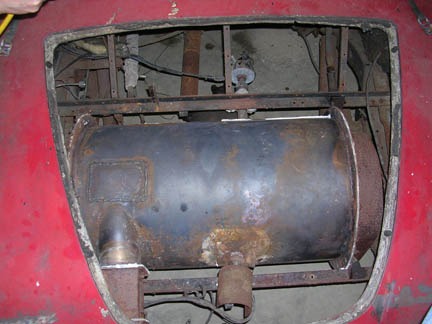
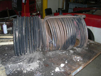
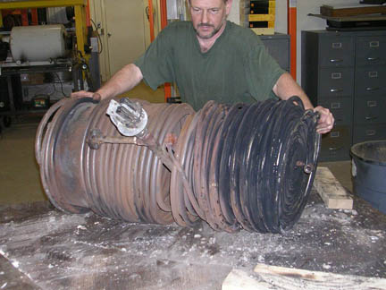
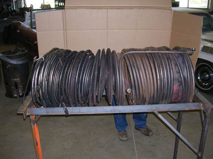
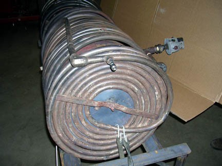
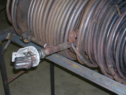
| Williams Victress Steam Generator. This was located in the trunk of the Victress bodied Williams car that had the 105 c.i.d. in-line four engine under the hood. The engine was advertised as producing 250 hp. The burner was reported to burn about 10 gallons per hour of kerosene. The burner and controls were missing from the boiler when it came to my shop. The boiler is a standard Doble “F” style boiler, with a water wall of helical coils and 13 pancake coils. The pancake coils are 5/8” od and the 2 superheater coils and the waterwall coils are ¾” od. Both made from 306 stainless steel. There were many pinhole leaks in the tubing probably caused by chlorine corrosion of the 306 from using city water. Also the inside | 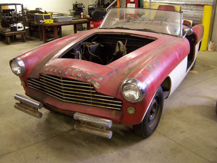 |
|
The Williams Victress |
||
 |
of the tubes were coated with carbon from the lubricating oil getting carbonized to the tubes. There was no oil-water separator. There were two commercially available Burling Instruments, Chatham, New Jersey quartz rod microswitch temperature controllers. The Burling company furnished me with a copy of the original invoice to the Williams Engine Company, Inc. dated 4/4/67 Model VD-2S that used a 13” quartz rod, normal open switch set at 800 F and normal closed switch set at 900 F. |
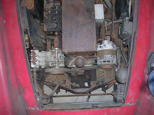
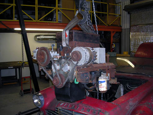
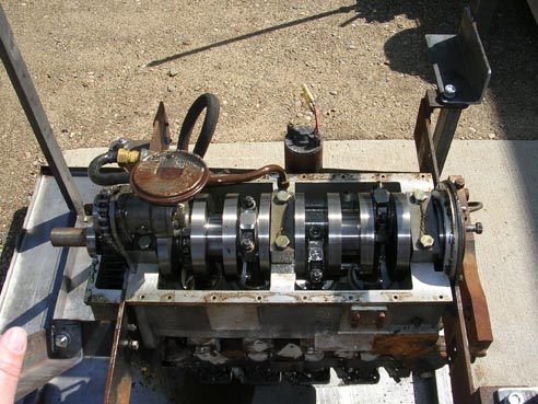
Williams 105 c.i.d. Victress Engine |
|||
| Williams 105 c.i.d. Victress car steam engine. This engine is on loan from the sons of Calvin Williams. The engine and car were made in about 1960 and driven extensively and shown to Congress during the clean air car hearings. The engine is of the final Williams’ design; four cylinder in-line with poppet valves, sliding cam with 4 forward and 1 reverse cam grinds. These were all high recompression uniflow engines with a patented pressure relief valveinto the steam chest. Extensive tests show an 8 pound water rate. When the engine is in the lower cutoff mode without the auxiliary exhaust valves open it was titled the “Williams Cycle”. | 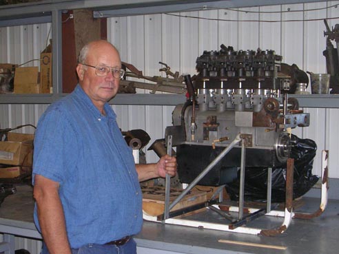 |
||
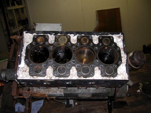
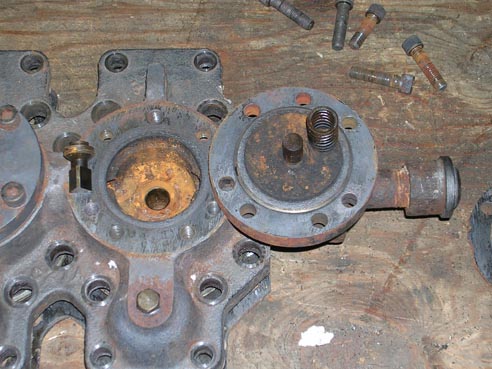
The final design was single acting cross head uniflow. This is seldom done by other steam engine designers. The cross head feature made the engine taller and more complex, however it had the advantage of keeping water out of the crankcase.
The basic Williams’ engine designs used high recompression uniflow engines,meaning that one third of the exhaust steam remained in the cylinder after the rest of it had exhausted through the exhaust ports. The clearance volume was designed so that thissteam was recompressed to boiler pressure. The original patent claimed that the recompression to boiler pressure raised the temperature several hundred degrees higher than incoming steam and thus there was an added efficiency. People have been arguing about this ever since. It appears to follow Professor Stumpf’s design work. |
|||
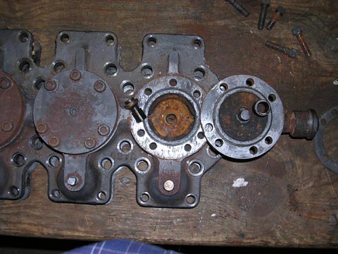
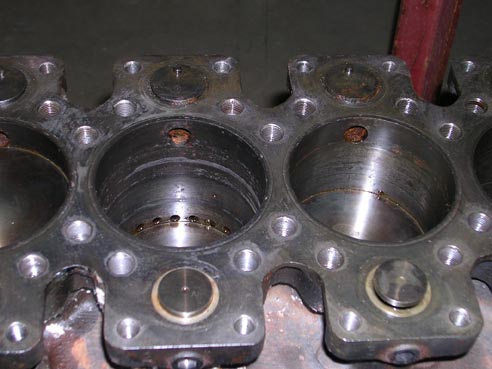
The Williams’ construction methods are well thought out and worth copying. The problem with a poppet valve steam engine is that the valve faces are on different planes about ¾” apart. This is because the intake valve is above the port going into the cylinder and the auxiliary exhaust valve is below the port. The problem was solved by bolting a short cylindrical piece onto the head. This plug fits down into the cylinder making the effective head an inch or so below
|
||
 |
|