
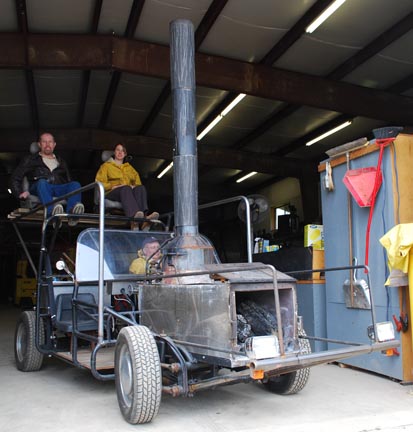
Tom Kimmel's Dune Buggy
Field-Tube Boiler, Dune Buggy Engine, First Version, New Photosof Swirl Fins
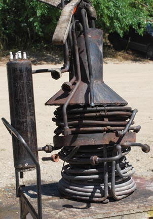
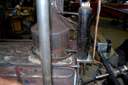
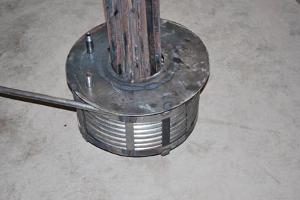
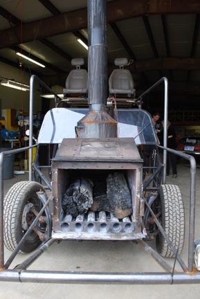
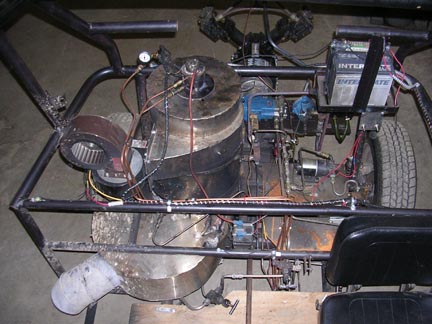
| This is the second or third incarnation of the boiler and about the middle of the fabrication on the frame. This has a wood fired boiler and a Strath Steam 2x2x2 piston valved engine belt driven into a VW drive train. This boiler is on display in the shop as it shows off my extensive knowledge of mono-tube wood fired boilers. Every possible design error was made in this boiler. It had no down comers and in consequence the bottom coils boiled dry, driving all of the water up into the water-steam separator drum where modestly hot water went into the engine. After a while a hole was burned in the superheater coil which caused much smoke and ash to envelope the vehicle. |
 |
||
|
August 2009: This boiler design was an attempt by me to make the perfect boiler. It had a jet circulating pump, a LaMont coil, a water level controller, a de-superheater section and a frusto-conical coil in an attempt to mimic the successful Scott-Newcomb design. | ||
| The next generation of boiler is a Field Tube Boiler (pdf file) so it has the largest downcomer that one can fit into a 2 ½” schedule 40 black iron pipe. There is plenty of room for steam separation in the new boiler and whenever we can figure out how to pump water it goes like the wind. As they say, money was spent and things were learned. | |||
| May 1, 2009: Tom Kimmel driving, he is about to leave the premisis. |
|
||
| (Note: Click on a picture for a larger view, then enlarge it through your browser.) | |||
|
This is the hydraulic powered coil winder that we use. Here shown with the cone that tapers from 6” at the top to 20” at the bottom. It is 20” high. With different attachments this winder does pancake, with any kind of spacing desired, helical, conical, and spring shaped such as is used in the Ofeldt. It grunts when 1” schedule 160 is being wound. |
|
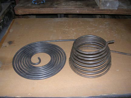 |
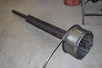
Some of the coils were frusto-conical and some were merely tightly wound pancake coils. The latter were pulled apart into a lower aspect ratio cone to separate the tubes a little more. We did not weld in or otherwise put spacers between the tubes because they were very springy when made. After running them dry a few times with a very intense wood fire they annealed and collapsed together, thus preventing any combustion gases to flow between them. |
|
|
|
|
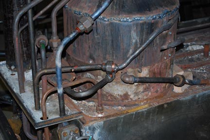
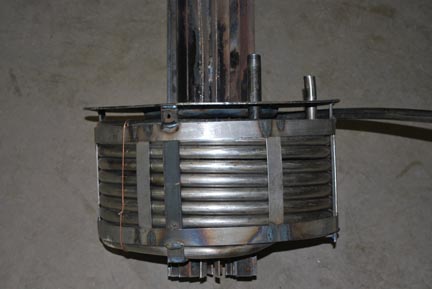
| Here is what this boiler looked like when plumbed in complete with a pre-heater section made from ¾” pipe welded to the fire box. | ||
|
||
|
|||
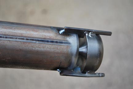
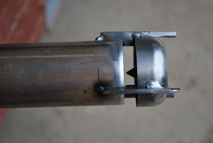
Taken at the September 2009 Annual Steam Automobile Club of American, Chicagoland Chapter Meet Here is the dune buggy with the fancy boiler installed. It ran poorly for a few times and then I burned a hole in the superheater section; that with a wood fire no less. After thinking about it I wrote a 4 page analysis of what was done wrong. It was easy to write that many pages because everything in the design was wrong. This analysis is in my blog (Posted August 8,2012). Mostly what was not done was to put in a downcomer somewhere. To begin with, a person will never know exactly what goes on inside a boiler, because it is too small to crawl inside and too hot besides. There is some conjecture involved in thus doing the analysis. Because it was a wood fire underneath the boiler, the heat evaporated all of the water in the lower coils pushing it up into the top of the water column. This gave a false reading to the water level sensors so no more water was pumped. Also it kind of defeated the whole purpose of the steam-water separator column and hot water was pumped into the engine instead of steam. Needless to say, it was a poor and erratic steamer. The Field Tube boiler ensued because it had the largest down comer a person could design into a boiler. |
|||
|
|||
Field-Tube Boiler |
||
|
||
 |
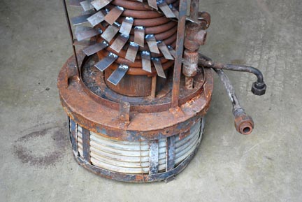
June 2010: These photos show the downcomer that is inside the Field Tube. This is a 4’ length of exhaust pipe of 2” O.D. The three little feet hold it an inch from the bottom of the 2 ½” main pipe. The legs also space it in from the pipe. The exhaust pipe is open at the top and bottom. We are never certain about what is happening inside a boiler, but here is what we think happens. The incoming pre-heated make up water is injected straight up at the middle of the center of the big pipe about an inch below the half rounded chunk of steel. It flows up around the outside of the exhaust pipe causing a flow up through this narrow channel past the hot tubing where steam bubbles are forming, thus causing more natural flow. When the hot water/steam bubble mixture gets to the top of the water level, about where the top of the exhaust pipe is located, the steam bubbles bubble off into the top two feet of the main pipe and the water flows down through the downcomer. The downward flow hits the half toroid shape and is re-directed up along the outside narrow passage. It seems to work and nothing has burned out yet. We think that nothing has burned out because there is always water in the pipe and as the water gets hotter with more steam bubbles formed the natural circulation flow gets faster, cooling down the metal. | |
 |
||
|
||
 |
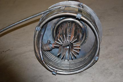
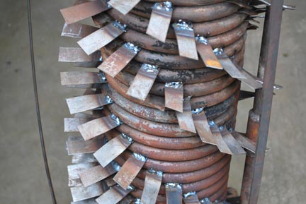
July 6, 2010: View down into the wood burning chamber. If you look closely you can see the swirl fins where the smoke and hot combustion products pass into the secondary combustion chamber. From that chamber the gases flow into the heat exchanger with the flow smoothness assisted by a round pipe welded around the opening to streamline the flow and thus avoiding "vena contracta". |
 |
 |
|
| July 6, 2010: View from the bottom of the Field Tube boiler. All of the combustion gases from the fire pass up in the space of 28 square inches. They are ducted to travel up past the fins, back down past a coil of ½” Schedule 40 black iron pipe and then reverse to go up the smoke stack. Incoming make up water counterflows into the helical coil and then into the bottom of the Field Tube. | ||
|
||
 |
 |
|
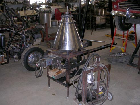
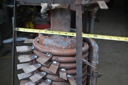
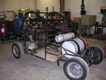
July 6, 2010: Field tube boiler: This began with a 6’ long piece of 2 ½” id schedule 40 black iron pipe. Then 2” flat stock was welded to the pipe lengthwise for fins. This was all mounted vertically and the top two feet was for steam/water separation. Helical stainless steel coils around the bottom were the superheater. At this point in the firebox the housing around the superheater glows red hot. Right underneath the coil stack is a bunch of stainless flat stock welded into swirl vanes. Therefore the smoke/combustion gases from the wood fire pass over the swirl vanes and are cleanly burned. |
||
 |
 |
|
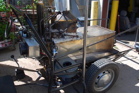
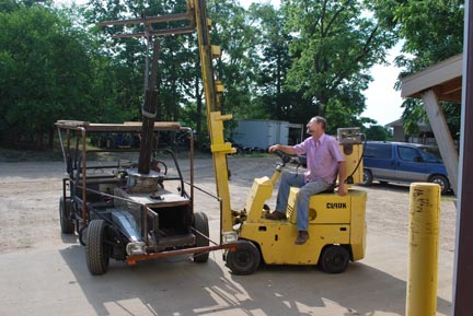
July 2010: Setting the boiler in place with the forklift. |
This picture is fuzzy because someone messed with my camera settings. |
 |
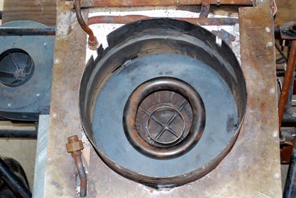
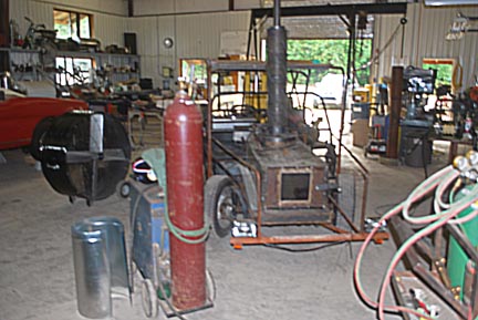
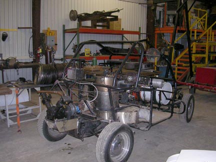
May 2009: The wood combustion chamber worked the best of all. In this photo the front plenum is off. There is a large dc motor driven centrifugal fan that pumps combustion air into the long plenum and this air goes back through the six tubes that lay in the bottom of the fire box. Every four inches the tubes have 3/16” diameter holes drilled into the sides. Thus all of the combustion air is blown sideways into the coal and ash layer at the bottom of the firebox. Thus all of the coals are burned up and most of the ash is blown up the chimney. Any wood thrown in on top just automatically burns. When the fan is turned off the fire dies down, but if there is a good bed of coals too much heat goes into the boiler. |
||
|
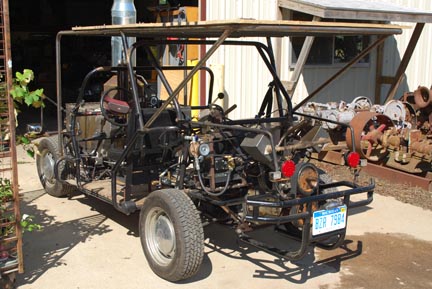
Dune Buggy Engine |
||
 |
 |
|
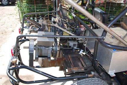
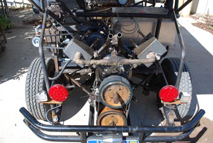
The Strath Steam V-2 doing a toothed belt drive to a jack shaft that goes through the VW pressure plate and clutch assembly. Note the double Vee belt driven jack shaft that runs the water pump, oil injection pump, Jabsco primer pump, and alternator. This is a bit of over-kill, but how a person designs the alpha model. One always wants things to work and to work well. After something is proven to work, anyone can hire an engineer to do engineering development work and simplify, lighten, and cheapen it up. |
||
|
|
|
Strath Steam V-2 mounted on the VW dune buggy using a toothed belt to drive a jack shaft that drives the clutch. The original VW trans-axle, clutch and pressure plate are used. A plate of 1/4” steel blocks off the bell housing. |
||
 |
 |
|
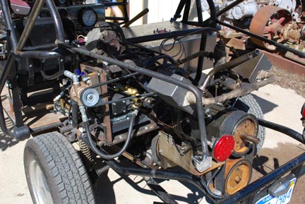
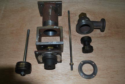
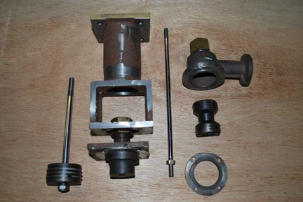
May 11, 2010: Due to human error, the engine was dropped on a concrete floor and the crosshead casting broken. Rod Muller of Strath Steam machined and shipped a replacement, here shown with the piston, piston rod packing, and piston valve. This is the Strath Steam Vee Twin Freedom This 2x2x2 engine can make 33 hp with the larger over-hung crankshaft. |
||
 |
 |
|
2nd Version - August 29, 2009 |
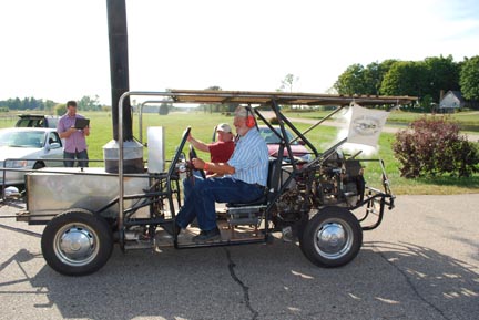
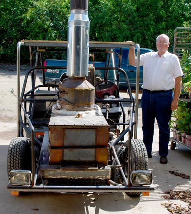
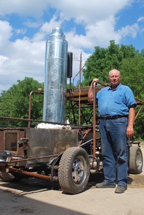
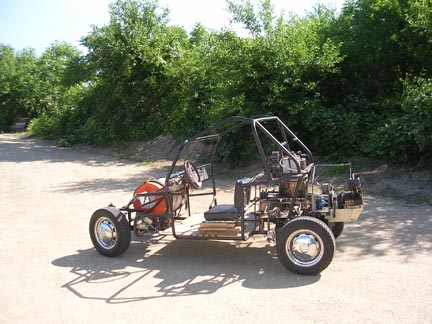
3rd Version - July 29, 2010: The proud boiler designer and the dune buggy. Note the water level controller off to the side of the boiler. Also note that the bulk of the boiler diameter is duct work and insulation. It still restricts forward viewing. |
|
|||
Dune buggy - First Version |
|||
| The first version of a steam powered dune buggy. We started with the steam generator from the SACA West Three-Wheeler Cushman conversion. The boiler was based on a Besler smoke coil and used a spinning cup burner burning gasoline. The control was pure Doble with a quartz rod and micro-switch controllers, all made according to Pete Barrett’s design. The original 24 volt war surplus fan motor quit and so we made do with two squirrel cage fans in series. An economizer was added slightly off center at the bottom. The engine is a Strath Steam 2x2x2 slide valve V-2. Water tank and fuel tanks are mounted up front. | 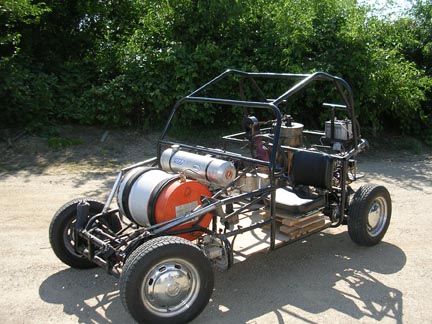 |
||
 |
 |
|
 |
 |